
| Model | JYG-SZGP6000 | |
| Input and output power | Input maximum power | 5600VA |
| Input maximum current | 26A | |
| Average power output of inductance | 64kVA | |
| Input voltage and frequency range | 190~260Vac 50/60Hz | |
| Operating frequency range | 750k~1200kHz | |
| cooling water | water pressure: | 300 kPa |
| flow | 1.5~2L/minute | |
| Input output interface | RS485 | 1 standard |
| Infrared temperature measurement interface (4-20mA current) | 1 | |
| 5V Input sampling interface | 1 | |
| 10V Input sampling interface | 1 | |
| Pwm input | 1 | |
| Foot input signal interface | 2 | |
| Switch output signal interface | 1 | |
| environment | Operating temperature | 0 ~ +55 °C |
| storage temperature | -25 ~ +70 °C | |
| relative humidity | 0~95%(No condensation) | |
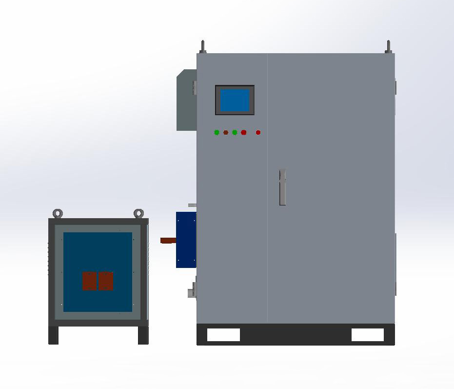
| size | Heating power supply | |
| Heated Head | ||
| Power and heating head wire length | 2 meters (standard), to be customized, please specify in advance | |
| weight | Heating power supply host | 15kg |
| Heated Head | 2kg | |
1. Foot switch
The foot switch is a signal used to control the startup of the heating power supply. Ports 5 and 6 are defined as switch 1, and ports 1 and 2 are defined as switch 2. In manual mode, when monitoring the power setting, two switches correspond to power setting 1 and power setting 2 respectively. In other modes, both switches can control the machine. When both switches are closed, switch 1 has a higher priority. The input signal is an open and closed passive signal.
2. 5V power signal
The 5V signal input port is connected to ports 16 and 17 through analog signals provided by the customer externally, where port 16 is a common ground and port 17 is a 5V voltage signal. This signal will go through an internal conditioning circuit, be sampled by the chip, and converted into the corresponding power. The proportional range of 0 to 5V corresponds to a maximum power of 6000W. For example, if a power of 3000W is required, a 2.5V DC signal can be sent.
3. 10V power signal
The 10V signal input port is connected to ports 13 and 14 through analog signals provided by the customer externally, where port 13 is a common ground and port 14 is a 5V voltage signal. This signal will go through an internal conditioning circuit, be sampled by the chip, and converted into the corresponding power. The proportional range of 0-10V corresponds to 0kVA to a maximum power of 6kVA. For example, if a power of 3kVA is required, a 5V DC signal can be sent.
4. PWM output signal
The PWM input ports are 3 and 4, where 4 is a common ground and 3 is a high potential signal. This signal is input to the control chip through an internal conditioning circuit, and the chip can continuously capture the cycle time T1 and duty cycle time T2 of the input PWM signal. By calculating the ratio of duty cycle time (T2/T1), 0 to 1 corresponds proportionally to a maximum power of 6kVA. Attention: This capture method requires a PWM frequency range of 1K~10K and a duty cycle range of 5%~95%. Exceeding this range may result in misjudgment. The high-level voltage must be greater than 6V.

5. Infrared temperature 4mA~20mA signal input
The infrared input signals are 19 and 20, where 19 is the ground of the infrared input and 20 is the infrared current signal. It is internally processed through a conditioning circuit and sent to the PLC communication of the control user. It can also be used as an upper computer interface to remotely control the operation of the machine. It is possible to move all the operating information, fault information, and settings of the machine to the user interface for operation, which greatly facilitates the user's understanding of the machine's operating status, setting control variables, and more flexible control of the machine. For users in need, they can contact the manufacturer to obtain the communication protocol.
Related Information

Mobile website
Our Product
Contact Us